Saturday, August 30, 2008
Thursday, August 28, 2008
Sunday, August 24, 2008
Project 2: Masterplan - Site Visit 1


Below are images of our site, this day was not a very nice one....very cold and windy!

Friday, August 22, 2008
Thursday, August 21, 2008
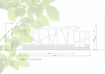
Project 1: RARE Architecture
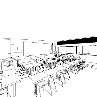
Project 1: RARE Architecture - 3D Interior
Project 1: RARE Architecture - 3D Exterior
Tuesday, August 12, 2008
Shading Windows

- Awning blind - Cut out 70% of the heat and easily lifted up to enjoy the natural light when the sun is off the window
- Roller Shutters - provide insulation and noise control as well as shading.
- Window tinting - cut the heat by 50% but reduces light all year around.
- Small tree, large shrub or a pergola with a vine outside of the windows - Deciduous varieties will drop their leaves to let in the winter sun. Planting can cut 60% of the summer heat from the window
- Simply hanging shade cloth from the outside of the window frame
- Add fixed awnings where there are no eaves
- Add shade sails to protect paved areas from the summer sun - paving heats up and continues to transfer heat to the house at night.
Interesting Facade


When you are looking at these pictures this might look like a modern piece of architecture, but after you’ll see the video attached below you’ll see that Flare is more than that. Flare is a modular, computer-driven system that creates a moving skin for the facade of a building and it was created by Christopher Bauder and Christian Perstl. The Flare units are made up of computer controlled metal flake bodies which are by supplemented pneumatic cylinders. A great futuristic outer shell for any building. Because of the shape and size of each unit it can be placed on any designed building.
Each metal flake reflects the bright sky or sunlight when in vertical standby position. When the flake is tilted downwards by a computer controlled pneumatic piston, its face is shaded from the sky light and this way appears as a dark pixel. By reflecting ambient or direct sunlight, the individual flakes of the FLARE system act like pixels formed by natural light. And now after you have an idea of how this system works, and you saw some pictures here is the most interesting part of this post, a video clip that shows the different patterns that are created based on how the tilting flakes reflect natural light.
Monday, August 11, 2008
Windows and Shading
WINDOWS AND SHADING
During Australia's Long, harsh summers, window shades such as awnings, sunscreens, shutters and louvres play an essential role in keeping the heat out.
But blocking out sun is not always desirable. For those in colder climates, sun streaming in through North-facing windows is an excellent source of sustainable heating energy. Also, sunlight is the most efficient and luminous of all types of internal lighting. You need to strike a balance between darkness and light
Louvres

Use adjustable slats that allow you to control the amount of sunlight and breeze that penetrates your home.
The slats can sit either horizontally or vertically and, depending on the design, can often be adjusted from inside your house.
They can be custom-made to suit almost any window and are available in a variety of materials such as timber, metal and plastic
North facing windows
It is recommended that around a third to a half of the north face of your home be glass, as it is very effective at trapping winter warmth and can be easily shaded from summer sun with correctly designed eaves.
To calculate the overhang needed, multiply the distance from the eaves-line down to the bottom of the window by 0.7. This will ensure the glass is adequately shaded from September until March. For cooler regions, multiplying by 0.4 will provide suitable shade from October until February. Deciduous trees and shrubs or creepers growing on an open pergola on the north face of a home can also provide window shading in summer, while allowing the sun through to warm your home once they've lost their leaves in winter. Alternatively, a solar pergola is designed to achieve the same result. It is important that shading devices, whether in the form of eaves, pergolas or appropriate landscaping, do not block the sun's access to the interior of your home during winter.
East and west facing windows
While east and west facing windows provide warmth in winter from the early morning and afternoon sun, they are difficult to protect from the sun in summer. This makes rooms on the east and west of your home uncomfortably warm, particularly west facing rooms which receive the hot afternoon sun. To keep cool in summer, it is recommended that the total area of east and west facing windows be kept to a minimum.
External shading devices provide some protection from the summer sun, with complete protection achieved only with full vertical screening, such as outside blinds or shutters. This is because the angle of sun will be close to horizontal early in the morning (east) and in the late afternoon (west), and only vertical screening can block the sun at these angles. Deciduous trees or vines growing on a trellis can also provide shading during summer.
South facing windows
South facing windows receive no direct sun in winter but will receive a few hours of morning and afternoon sun in summer months. For this reason, they lose heat in winter and gain some undesirable heat in summer. South facing windows should be large enough to allow good ventilation and light to enter the home without losing too much heat in winter.
Vertical elements such as external screening or landscaping in conjunction with internal blinds will be most effective at shading south facing windows, since the majority of this sun is at low angle. Basic 'eaves overhang' in combination with internal window treatments will also assist solar control to south facing windows. This is because in mid summer the sun can fall on an unshaded southern façade for approximately 4 hours in the morning and 4 hours again in the afternoon. For the more northerly latitudes (eg Geraldton) provision of shading to south facing windows is even more important. This is because at this latitude there can be an additional 45 minutes of mid summer sun falling on the south face of a building, morning and afternoon.
Internal window treatments
While external window treatments are the best way to reduce summer heat gain, internal window treatments are most important for reducing winter heat loss. A window can lose heat five to ten times faster than an equivalent area of wall. This heat loss can be minimised by keeping warm air inside the room away from cold windows.
Closed curtains can be effective insulators and should be made from a heavy fabric with insulating backing for maximum effectiveness. They need to be long enough to reach the floor and should include a closed pelmet. The pelmet is an integral part of the curtain as it reduces air circulation and consequent heat loss through the window glass during winter and heat leakage into the home during summer when the curtains are drawn.
Tinted glass and reflective films
Tinted glass and reflective films absorb and reflect heat, keeping your home cooler. However, be aware that using them reduces the amount of light and heat entering rooms in winter as well as in summer. During summer the glass itself also becomes hot as it absorbs energy, which will cause some heat to be radiated into the room. These products may be useful where large areas of east and west glazing are unavoidable due to design reasons. However, tints and films will generally not reduce heat gain as much as external shading.
Double glazing
Two panes of glass separated by at least 10 mm can reduce winter heat loss but is generally only cost effective in situations with high heating requirements. Double glazing can also reduce conductive summer heat gain. However, when exposed to sun double glazed windows will still allow significant heat transfer, which means that full shading is still required.
Information sourced from: http://www.sedo.energy.wa.gov.au/pages/windows.asp
Screw Piling
SCREW PILING

Above is a image of screw piles.
Below is a image of the screw piles being driven in.

What is a screw pile?
It is a circular hollow section of steel (shaft) with one or more tapered steel plates (helix's) strategically welded to the shaft which is in turn wound into the ground using rotary hydraulics for the purpose of compression piles and tension anchors.
Connection to footing:
Screwpile connection to a typical pilecaps and footings is via either Y-bars placed through the top of the pile or e-flanges. Both are left exposed into the cap / footing.
The advantages of screwpiling are:
- Vibration free installation (no interference to adjacent buildings/structures)
- Very fast installation (actual pile installation average of approx. 5 minutes
- Minimal noise disturbance to adjacent environments
- No de-watering
- No concrete
- No Reinforcement
- No spoils
- No liners
- Versatile
- Re-Usable
Applications:
- replacing bored piers
- Replacing blinding concrete
- Replacing concrete pads and stumps for timber floors
- Angle of repose for easements and sewers
- for protection of tree roots and as root barriers
- for underpinning new or existing structures
- for eco-sensitive sites
The pile consists of a high tensile 350 to 400 Grade steel shaft, with a single or multiple Helix Plate welded to the base of the shaft and a point of attack "bit" at the end, to assist in penetrating the soil profile. The pile is screwed into the soil profile by a hydraulic drive motor which is suspended off the boom of the excavator.
A pressure gauge is mounted in the cab for the operator to read the "torque" being generated as the pile is screwed into the soil profile. The torques are measured and recorded by the installer on the engineer's project log.
The design requirements for the torques are test proven from soil bearing capacity to torque relationships which are related to Static Load results and C.P.T. comparisons.
Information sourced from: http://www.pilingsystems.com.au/what_is.shtml and www.instant.com.au/


